
Gas Turbine Probe Traverse System
The two-axis radial and yaw traverse actuator system was developed from an initial requirement to traverse an aerodynamic probe in the high temperature gas stream of an industrial gas turbine test rig. The resulting traverse system has a high positioning accuracy, high stiffness and a high level of reliability, whilst operating in a harsh test environment. Since its initial conception, the design has been demonstrated and proven in a large number of turbine installations for different applications from air-flow laboratory test equipment thro’ development test gas turbines to full aero-engine pylon testing and production industrial gas turbine testing. Due to its modular construction, it has also been adapted into a number of different configurations, including complex 3 and 4 axis traverses. However, the basic traverse system provides an accurate, reliable and rugged means of positioning a wide variety of instruments and probes inside a space envelope for all sorts of potential applications.
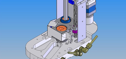
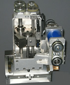
Main Traverse Actuator
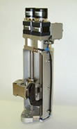
The basic system consists of the two axis traverse actuator with a PC and controller. The measuring instrument, often an aerodynamic probe or pyrometer for gas turbine testing, is fitted on to the yaw module carriage (shown in the above image), which traverses both up and down the actuator, via the radial drive, and rotates, via the yaw drive. The radial axis consists of a carriage driven by a precision ballscrew and supported by a secondary splined shaft. A stepper motor drives the lead-screw, either directly or indirectly through a belt drive - depending on the detail design option chosen, with incremental encoder position feedback.
 A splined shaft rotates the yaw axis module on the carriage, via either a unique metal band drive system, or pre-loaded precision toothed belt, eliminating backlash. Again, the shaft is either directly or indirectly driven by a stepper motor and harmonic drive with incremental encoder position feedback.
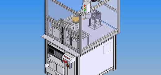
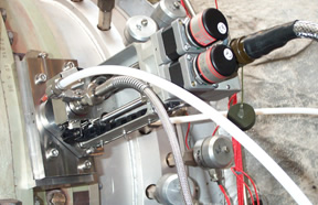
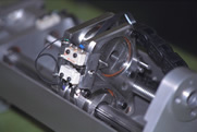
As mentioned, the design is modular and can be readily adjusted for different installation configurations. An indirect, toothed belt stepper motor drive is often used, resulting in a more compact configuration. Also, additional axes can be added, as required. Both of these options are shown in the following two traverse images. One shows a compact 2 axis traverse designed for testing the HP and IP turbine in the confined space of an aero-gas turbine and the other, a 3 axis traverse for a complex traversing requirement inside a cold flow industrial turbine test rig.
Provision can also be made for applying pressurised cooling air at the probe interface, temperature sensors and a variety of mounting adaptors.
Finally, the linear traverse can be designed from below 50mm to in excess of 300mm with the baseline configuration. For larger traverse requirements, a different outer casing is required. The largest traverse produced to-date is over 1000 mm.
A typical traverse specification is as follows:
- Typical Linear Accuracy = ± 0.05 mm to ± 0.1 mm
- Design ‘Rated’ Load = 500 N to 800 N @ 10 mm/s
- Maximum Speed = 25 mm/s
- Angular Range = +/- 165°
- Typical Angular Accuracy = ± 0.05° to ± 0.10°
- Design ‘Rated’ Torque = 8 Nm to 10 Nm @ 15 °/sec
- Maximum Angular Speed = 25 °/sec
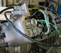
Large Two Axis Traverse System
Connecting Cables
Cables are rated for 70°C continuous running with MIL spec connectors and internally screened to minimise EMI. Cables can be armoured, if required.
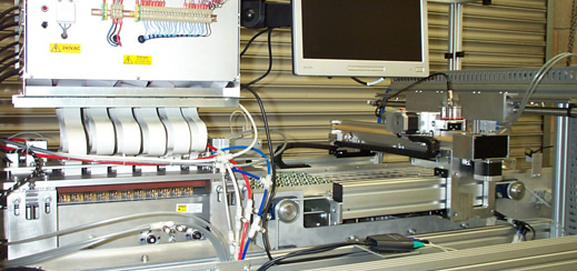
PC Based Control System & Software
A number of options are available for the control system. The baseline design uses standard industrial motion controllers, whilst the option to use National Instruments drives also exists. The controller cabinet is a 19” rack mounting and can be supplied pre-installed in a 19” cabinet, along with a 19” rack mounted industrial PC. This will have spare slots that can accept data acquisition cards etc. A rack mounted keyboard and mouse are also provided. Other PC options are available, as required.
The control software was written for the Traverse System using standard National Instruments ‘LabView’. It allows both manual and fully automated running through a ‘position table’ and can be configured to interface with main DAQ systems, as required. The software currently allows independent or concurrent motion of up to four (two axis) actuators. However, this could be modified, as required.
An additional Auto-Yaw and Data Acquisition (DAQ) Option is also available.